Showing posts with label OptiX OSN 3500. Show all posts

Thursday, October 20, 2016

An NE Became Unreachable to the NMS After Line Boards Were Cold Reset

Lower-rate multiport line boards preempted DCC resources of higher-rate line boards after line boards were cold reset during an NE upgrade or expansion. As a result, the NE became unreachable to the NMS. The fault was rectified by releasing DCC resources on lower-rate line boards.

Fault Type

  • DCN fault
  • DCC_CHAN_LACK

Symptom

Before an NE upgrade or expansion, the NE did not report any alarms, and DCC communication was normal. After an NE was upgraded or expanded, line boards reported the DCC_CHAN_LACK alarms, and the NE became unreachable to the NMS.

Cause Analysis

During an NE upgrade or expansion, line boards were cold reset, and DCC resources were re-allocated. The lower-rate line boards preempted DCC resources of the higher-rate line boards. As a result, the NE became unreachable to the NMS.

Procedure

  1. Checked whether there were any bit errors in DCC byte transmission. The transmit end sent DCC bytes, but the receive end did not receive any. Therefore, this issue was not related to bit errors.
  2. Went to the site and checked the NE status.
    1. Connected a PC directly to the NE, and logged in to the NE.
    2. Checked the ECC protocol settings. The settings were correct. Therefore, this issue was not related to the ECC protocol settings.
    3. Performed a switchover from the active SCC board to the standby SCC board. The DCC_CHAN_LACK alarms persisted. Therefore, this issue was not related to an SCC board.
    4. Removed the lower-rate line boards. The higher-rate line boards immediately began to transmit data. The DCC_CHAN_LACK alarms cleared, and NEs communicated properly with each other. It was inferred that the lower-rate line boards preempted DCC resources of the higher-rate line boards, blocking the NMS from reaching the NE.
       NOTE:
      • Generally, an SCC board supports multiple DCC working modes, and some DCC working modes provide more DCC resources.
      • In the default DCC working mode for the N1GSCC board, the D1 to D3 bytes function as physical transmission channels and 10 optical ports are DCC-enabled.
      • Generally, a lower-rate line board has multiple optical ports. For example, an SLT1 board has 12 optical ports. After the line boards were cold reset, DCC resources were re-allocated. The lower-rate line boards preempted DCC resources of the higher-rate line boards. The higher-rate line boards failed to obtain DCC resources, blocking the NMS from reaching the NE.
    5. Re-installed the lower-rate line boards.
  3. Checked for the DCC_CHAN_LACK alarm on the NMS after the NE was running properly. The DCC_CHAN_LACK alarm persisted, and the NE became unreachable again.
  4. Released DCC resources from optical ports on the lower-rate line boards. The optical ports on the higher-rate line boards restored to transmit data. The DCC_CHAN_LACK alarm cleared, and the NE became reachable from the NMS. It was determined that the lower-rate line boards preempted DCC resources of the higher-rate line boards, blocking the NMS from reaching the NE.
     NOTICE:
    Before an NE upgrade or expansion, properly allocate DCC resources. Specifically, release some DCC resources from lower-rate multiport line boards so high-rate line boards can obtain sufficient DCC resources upon cold resetting.

Friday, October 7, 2016

Certain Ports on the N1SLQ4 Board Are Unavailable due to Bus Wiring Limitation of the Cross-Connect Board

Certain ports on the N1SLQ4 board are unavailable due to the bus wiring limitation of the cross-connect board. This problem is solved by reinstalling the N1SLQ4 board.

Fault Type

Cross-connect unit

Symptom

The OptiX OSN 3500 is configured with the N1SXCSA board. Two N1SLQ4 boards are installed in slots 4 and 15, but only the former two optical interfaces of the boards are available.

Cause Analysis

When planning the slots of boards, you need to consider the access capacity of slots, the bus wiring of the cross-connect board, and the bus rate of the board.
  1. The OptiX OSN 3500 is configured with the N1SXCSA board. The access capacities of slots 5 and 14 are 5 Gbit/s. The total rate of the ports on the N1SLQ4 board is 2.5 Gbit/s. Therefore, the problem is not caused by access capacity limitation.
  2. The N1SXCSA board can adapt to 622 Mbit/s buses and 2.5 Gbit/s buses.
  3. The bus rate of the N1SLQ4 board is 622 Mbit/s, so four 622 Mbit/s buses are required to support the four optical interfaces on the board. However, slots 4 and 15 provide only two buses respectively. Therefore, only the former two optical interfaces on the boards are available.

Procedure

  1. Reinstall the N1SLQ4 boards into slots 5 and 14. Slots 5, 6, 13, and 14 provide four buses. Then, all optical interfaces on the boards are available.

Related Information

On the OptiX OSN equipment, two types of backplane buses are available, namely, 622 Mbit/s and 2.5 Gbit/s. The bus specifications of the OptiX OSN equipment are as follows:
  • The OptiX OSN 1500 supports 622 Mbit/s buses only.
  • The OptiX OSN 2500 supports 622 Mbit/s buses only.
  • When configured with the GXCSA, EXCSA, or UXCSA/UXCSB, the OptiX OSN 3500 supports 622 Mbit/s buses only. When configured with the SXCSA/SXCSB, IXCSA/IXCSB, or FXCSA, the OptiX OSN 3500 can adapt to 622 Mbit/s buses and 2.5 Gbit/s buses.
  • The OptiX OSN 7500 can adapt to 622 Mbit/s buses and 2.5 Gbit/s buses.

MORE BLOG:

Wednesday, September 28, 2016

LASER_MODE_ERR Caused by the Incorrect Optical Module on the SL16 Board

The LASER_MODE_ERR alarm occurs because an incorrect optical module is used on the SL16 board. This problem is solved by replacing the incorrect optical module with a correct one.

Fault Type

LASER_MODE_ERR

Symptom

The SL16 board on the OptiX OSN 3500 reports the LASER_MODE_ERR alarm. The SL16 board is interconnected with a 2.5 Gbit/s optical interface and does not report any abnormal alarm about optical signals.

Cause Analysis

Query the board manufacturing information.

shows the query result.
The query result indicates that the optical module on the SL16 board is MXPD-243S and has a rate of 622 Mbit/s. In fact, the optical module is a GE module.
The board reports the LASER_MODE_ERR alarm because the rate of the optical module (1.25 Gbit/s) is different from the rate of the board (2.5 Gbit/s). When you query the SDH signal rate of the optical module, the maximum rate of the optical module is the maximum rate lower than 1.25 Gbit/s. Therefore, the query result indicates that the maximum rate of the optical module is 622 Mbit/s.

Procedure

  1. Replace the original optical module with a 2.5 Gbit/s optical module. The SL16 board receives and transmits STM-16 signals, so the 2.5 Gbit/s optical module matches the board. Then, the LASER_MODE_ERR alarm clears.

Tuesday, September 27, 2016

Services on SNCP Rings Become Unavailable due to Fiber Misconnections

Services on two SNCP rings become unavailable due to fiber misconnections. This problem is solved by reconnecting the fibers.

Fault Type

SNCP fault

Symptom

NE C (the OptiX OSN 3500) forms two 155 Mbit/s SNCP rings with two groups of STM-1 optical interfaces. Ring 1 connects NE A (the OptiX Metro 1000) and Ring 2 connects NE B (the OptiX Metro 1000). NE A and NE B send 2 Mbit/s services respectively to port 1 and port 2 on NE D. Figure 1 shows the network diagram.
Figure 1 Correct SNCP network diagram
After the fibers on Ring 1 and Ring 2 are cut over, NE C does not report any alarm or performance event. The services on Ring 1 and Ring 2, however, are interrupted.

Cause Analysis

Possible causes of the problem are as follows:
  • The services are incorrectly configured.
  • The loopback of services is not released.
  • Fibers are misconnected.

Procedure

  1. Check the service configuration and confirm that the service configuration is correct. In addition, the cutover does not change the services.
  2. Perform an outloop respectively at the tributary ports on NE A, NE B, and NE D. The outloops are normal, indicating that the NEs are connected properly.
  3. Perform an inloop for the 2 Mbit/s services on NE A and test the signals at Port 1 on NE D. The test reports the OOF alarm.
  4. Deactivate the services that NE D receives from NE B. As a result, the APS switching occurs on NE A. In addition, the services on NE A recover. It can be inferred that fibers are misconnected.
  5. Check the fiber connections between NE A and NE C, between NE B and NE C by modifying the J0 byte. It is found that one pair of fibers on Ring 1 and one pair of fibers on Ring 2 are not connected as shown on the NMS. Figure 2 shows the incorrect SNCP network diagram.
    Figure 2 Incorrect SNCP network diagram
  6. Reconnect the fibers according to the fiber connections before the cutover. Then, the fault is rectified.

Related Information

If the transport equipment does not report any alarm or performance event, the network is not necessarily normal on the transport side.
Therefore, after a cutover that involves fibers connections on the transport side, you need to carefully check the fiber connections and ensure that the fiber connections are the same as before the cutover.
Try to use meters for troubleshooting and judge based on the testing results of meters.

MORE BLOG:

Description on the flow control of the NG SDH EFT data board

Tuesday, August 16, 2016

62COA Cannot Amplify Optical Power and OUT_PWR_ABN Is Reported

When the input optical power is higher than the locked output optical power, the 62COA cannot amplify optical power but attenuates it by 2 dB. This fault can be rectified by changing the optical power input from the upstream site.

Fault Type

OUT_PWR_ABN

Symptom

  • When the input optical power of the case-shaped optical amplifier 62COA is between -43 dBm and -20 dBm but higher than the locked output optical power, the output optical power is attenuated by 2 dB. The 62COA malfunctions.
  • The NE reports the OUT_PWR_ABN alarm.

Cause Analysis

The locked output optical power of the 62COA is -26 dBm by default. When the input optical power of the 62COA is higher than -26 dBm, the 62COA malfunctions.

Procedure

  1. Add an optical attenuator to the upstream transmit site. It is recommended that the input optical power of the 62COA be a value between -39 dBm and -26 dBm.

Related Information

Locked output optical power parameter applies to the case-shaped optical amplifier 62COA only.

MORE BLOG:

When customized for North America unable to configure OSN1800.


GSCC Reports HARD_BAD Due to Backplane Fault

Due to backplane faults, the GSCC board is not running properly and keeps reporting the HARD_BAD alarm. After the subrack is replaced, the alarm clears.

Fault Type

HARD_BAD

Symptom

The GSCC board keeps reporting the HARD_BAD alarm.

Cause Analysis

When parameter 5 in the HARD_BAD alarm parameters is 0x04, the NMS displays that an Ethernet communication port between boards is faulty. There are three possible causes:
  1. The GSCC board is faulty.
  2. The auxiliary interface board is faulty.
  3. The backplane is faulty.

Procedure

  1. Remove the standby GSCC board. The HARD_BAD alarm persists. So, the fault should be located on the active GSCC board, auxiliary interface board, or slot 17.
  2. Replace the active GSCC board in slot 17. The HARD_BAD alarm persists. So, the active GSCC board cannot be faulty.
  3. Exchange the active GSCC board in slot 17 with the standby GSCC board in slot 18. The standby GSCC board in slot 17 reports the HARD_BAD alarm. So, the fault should be located on the standby GSCC board, auxiliary interface board, or slot 17.
  4. Replace the standby GSCC board in slot 17. The HARD_BAD persists. So, the standby GSCC board cannot be faulty.
  5. Replace the auxiliary interface board. The HARD_BAD alarm persists, so the fault does not pertain to the auxiliary interface board. The fault should be located on slot 17.
  6. Check whether the backplane has bent pins.
  7. Replace the subrack. The HARD_BAD alarm clears.

Thursday, July 14, 2016

When Failed to Create ATM Services

ATM services fail to be created, thus failing to realize the protection. You need to add the two connections into the protection group.

Fault Type

Configuration_Problem

Symptom

After you create two connections that have the same source but different sinks, or that have the same sink but different sources, the service of a connection fails to be created.
The service fails to be created. The protection fails to be achieved accordingly.

Cause Analysis

The second connection takes effect only after you add the two connections that have the same source but different sinks, or that have the same sink but different sources into the protection group.

Procedure

  1. Add the two connections into the protection group.

How to do when Mismatching Between MA Groups and Associated VCTRUNKs, Hence Causing the Binding Failure?

IMA groups fail to be bound with associated VCTRUNKs. You need to configure IMA groups to match with associated VCTRUNKs.

Fault Type

Configuration_Problem

Symptom

The principle of binding VCTRUNKs is met, but VCTRUNKS fail to be bound.

Cause Analysis

Mutual check relation exists between IMA groups and associated VCTRUNKs.

Procedure

  1. If IMA groups are symmetrically configured, make sure that the mapping VCTRUNKs are symmetrical.
  2. If VCTRUNKs are nonsymmetrical, make sure that the mapping IMA groups are nonsymmetrical.

Failing to Create the 622 Mbit/s Service

The ATM 622 Mbit/s service fails to be created. You need to adjust the VCTRUNK that is bound with VC-4.

Fault Type

Configuration_Problem

Symptom

The 622 Mbit/s service fails to be created.

Cause Analysis

The four bound VC4 virtual connections are in the first ATM processing unit. The source end or sink end of the created connection belong to the same external port. The bandwidth used at the source end and sink end is 622 Mbit/s x 2 = 1244 Mbit/s, which exceeds the maximum bandwidth of a single ATM processing unit.

Procedure

  1. Delete the VCTRUNK that is bound with VC4 timeslots 1 -4.
  2. Set up the VCTRUNK that is bound with VC4 timeslots 5 -8.

Thursday, June 2, 2016

Service Becoming Unavailable When the IMA Protocol and VPRing Protocol Are Configured at the Same Time

Service becoming unavailable when the IMA protocol and VPRing protocol are configured at the same time. You need to rectify the faults at the opposite end.

Product

Fault Type

Configuration_Problem

Symptom

If the IMA protocol is configured for symmetrical operation, and if the VPRing protocol is configured for single-ended switching, the services are unavailable in the case of hybrid configuration.
The services become unavailable.

Cause Analysis

The IMA protocol is configured for symmetrical operation, and the VPRing is configured for 1+1 or 1:1 single-ended switching. In this case, if a switching event occurs to the VPRing protocol, and if the IMA protocol detects the failure for the opposite end to receive signals, the local end stops transmitting cells.

Procedure

  1. Rectify the faults at the opposite end.

Tuesday, May 3, 2016

Remotely Checking the Correctness of the DCM Installation

Remotely checking the correctness of the DCM installation.

Product

Fault Type

DCM Module

Symptom

In the hardware installation of the OptiX BWS 1600G, because of the mis-operation of engineers, the DCM at some sites may be installed incorrectly. For example, the two directions of a DCM in an OLA site are: from east to west, C1 (20 km) and from west to east, C3 (60 km). If the two directions are installed incorrectly, the service cannot be provisioned smoothly. Hence, we need to check whether the two directions are installed in the reverse manner.

Cause Analysis

It is time-consuming to check the correctness of the DCM installation on site. We can remotely check the OAU optical power to determine whether DCM is installed correctly. The OAU provides the detection and report of optical power at five points on the board. Optical interface 3, corresponding to optical interface RDC, detects the input optical power in the middle of the board; Optical interface 5, corresponding to optical interface TDC, detects the output optical power in the middle of the board.


Because DCM is installed between TDC and RDC of the OAU, the difference in optical power between interface 5 and interface 3 is the DCM insertion loss. Because the DCM insertion loss is basically fixed, one knows what DCM model is installed according to the insertion loss.

Procedure

  1. Query the east-to-west OAU optical power and the difference in optical power between interface 5 and interface 3 is calculated to be 1.6 dB.
  2. Query the west-to-east OAU optical power and the difference in optical power between interface 5 and interface 3 is calculated to be 5.3 dB.
  3. This shows that the east-to-west is DCM (C1) and the west-to-east is DCM (C3). The two DCMs are installed correctly. There is no need to conduct on-site operations.

Reference Information

  • The engineers must be trained before performing hardware installation. The engineers are required to install the hardware according to the cabinet fiber wiring diagram in the engineering design. Observe the label on the fiber jumper that is threaded to the DCM frame from the subrack. Note that the DCM model is indicated on the label.
  • If a problem occurs during the hardware installation, do not rush to the site. Consider whether the equipment can be remotely checked.
  • If the problem can be remotely resolved, use the remote method. If remote troubleshooting is impossible, the engineer has to go to the site to resolve the problem.

Monday, May 2, 2016

Remotely Checking the Correctness of the DCM Installation

Remotely checking the correctness of the DCM installation.

Product

Fault Type

DCM Module

Symptom

In the hardware installation of the OptiX BWS 1600G, because of the mis-operation of engineers, the DCM at some sites may be installed incorrectly. For example, the two directions of a DCM in an OLA site are: from east to west, C1 (20 km) and from west to east, C3 (60 km). If the two directions are installed incorrectly, the service cannot be provisioned smoothly. Hence, we need to check whether the two directions are installed in the reverse manner.

Cause Analysis

It is time-consuming to check the correctness of the DCM installation on site. We can remotely check the OAU optical power to determine whether DCM is installed correctly. The OAU provides the detection and report of optical power at five points on the board. Optical interface 3, corresponding to optical interface RDC, detects the input optical power in the middle of the board; Optical interface 5, corresponding to optical interface TDC, detects the output optical power in the middle of the board.


Because DCM is installed between TDC and RDC of the OAU, the difference in optical power between interface 5 and interface 3 is the DCM insertion loss. Because the DCM insertion loss is basically fixed, one knows what DCM model is installed according to the insertion loss.

Procedure

  1. Query the east-to-west OAU optical power and the difference in optical power between interface 5 and interface 3 is calculated to be 1.6 dB.
  2. Query the west-to-east OAU optical power and the difference in optical power between interface 5 and interface 3 is calculated to be 5.3 dB.
  3. This shows that the east-to-west is DCM (C1) and the west-to-east is DCM (C3). The two DCMs are installed correctly. There is no need to conduct on-site operations.

Reference Information

  • The engineers must be trained before performing hardware installation. The engineers are required to install the hardware according to the cabinet fiber wiring diagram in the engineering design. Observe the label on the fiber jumper that is threaded to the DCM frame from the subrack. Note that the DCM model is indicated on the label.
  • If a problem occurs during the hardware installation, do not rush to the site. Consider whether the equipment can be remotely checked.
  • If the problem can be remotely resolved, use the remote method. If remote troubleshooting is impossible, the engineer has to go to the site to resolve the problem.
More related:

Sunday, April 24, 2016

Notice on Prewarning for Occasional Hot Patch Installation Failures for the Active System Control Boards

Product Line
Transport network
Product Family
Product Model
Release Date
2014-09-30
Severity
Minor
Urgency
Non-urgent
Versions Involved
All V100R010C03 versions (including static and patch versions) earlier than V100R010C03SPC220
Devices Involved
Application Scope 
In and out of China
Operation Category
Prewarning
Prewarning ID
21204
Operation Requirements
Learn how to prevent the same issue.
Expected Completion Date

Manpower Required

Contacts
Product Line Contact
Liu Haiyong (employee ID: 00148879)
Xu Kai (employee ID: 00287661)
Regional Office Rectification Contact

Representative Office Rectification Contact


Keywords:
Active system control board, hot patch installation failure
Summary:
When the active system control board on an NG-SDH product of a version listed in Versions Involved in the preceding table starts from a reset, there is a possibility that the patch package module cannot obtain the software version of the active system control board. As a result, software version verification fails when a patch is loaded, and the patch cannot be installed on the active system control board.
[Problem Description]
Trigger condition:
1. A patch of a version listed in Versions involved in the preceding table is installed on OSN 1500/OSN 2500/OSN 3500/OSN 3500 II/OSN 7500 equipment.
2. The system control board starts from a reset.
Symptom:
A hot patch cannot be installed on the active system control board.
Identification method:
1. The version of an OSN 1500/OSN 2500/OSN 3500/OSN 3500 II/OSN 7500 NE is V100R010C03.
3. Query the NE version by running the following command or using the NMS.


4. Run the following command to query the version of the active system control board recorded in the patch package:
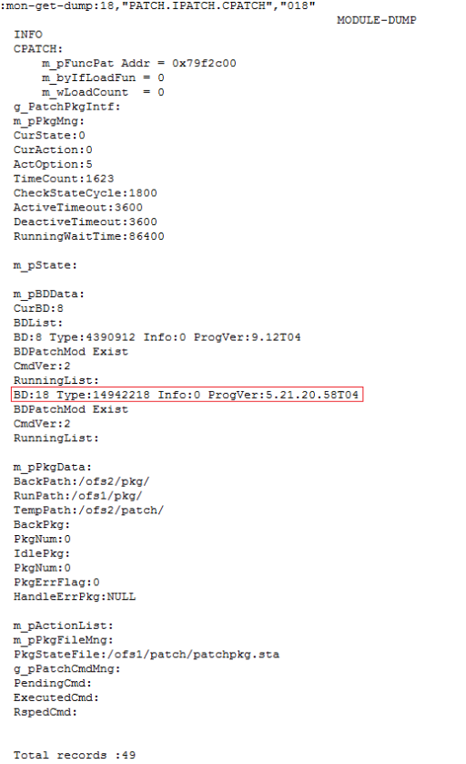
:mon-get-dump:18,"PATCH.IPATCH.CPATCH","018"
The numbers in red represent the slot ID of the active system control board.
The command output indicates that the version of the active system control board is empty (the ProgVer field behind the slot ID of the active system control board is empty, as shown in the following figure).
[Root Cause]
After the active system control board starts from a reset, the patch package module issues a command to the software management module to query the software version. Because the CPU is busy, the software management module does not send the software version to the patch package module within the timeout period. As a result, the query for the software version times out, and the software version of the active system control board recorded in the patch package is empty. When the patch is installed, the NE software verifies the software version of the active system control board and finds that it is not consistent. The verification fails, and the installation of the hot patch for the active system control board is stopped.
[Impact and Risks]
A patch cannot be installed for the active system control board. Issues which can be resolved by installing a hot patch remain unresolved.
Measures and Solutions
Preventive measure:
Before installing a patch, run the following command to query whether the version of the active system control board recorded in the patch package is empty:
:mon-get-dump:18,"PATCH.IPATCH.CPATCH","018"
The numbers in red represent the slot ID of the active system control board.
In normal cases, the ProgVer field behind the slot ID of the active system control board records the detailed version number, as shown in the following figure.

When exceptions occur, the ProgVer field behind the slot ID of the active system control board is empty, as shown in the following figure.


If the version is empty, warm reset the active system control board, or perform an active/standby switchover between the system control boards (for details, see recovery measures). Then, query the software version of the active system control board again to ensure that the software version is recovered.
Recovery measures:
5. When possible, warm reset the active system control board.
6. If an NE houses an active system control board and a standby system control board, a patch has been installed on the standby system control board, and batch backup operations on the active and standby system control boards are complete, then manually trigger an active/standby switchover between the active and standby system control boards to resolve the issue when possible.
Solution:
Upgrade the NE software to V100R010C03SPC220 (which will be released in the first quarter of 2015) or a later version, in which the patch going-online mechanism of the active system control board is optimized and the query for the software version of the active system control board will not time out.
[Rectification Scope and Time Requirements]
N/A
[Rectification Instructions]
N/A
[Appendix]
N/A
[Inspector Applicable or Not]
Use the inspector to check the entire network. Upon detection of an NE that is suspected to have this issue, it is recommended to perform the recovery measures and then upgrade the NE.
Version of the inspector: SmartKit V200R009C00SPC201 or later
Inspector upgrade package:
Common_Inspector_V200R009_ON_20140909163631680.exe
Inspector_V200R009_ON_OptiX OSN 1500, OptiX OSN 1500+,+_20140909163631780.exe
Test case name (which will be released at the end of September 2014): Check whether the version number of the active system control board cannot be obtained and the hot patch cannot take effect.

More related:

Installing the U2000 Client on Windows