Showing posts with label SDH. Show all posts

Thursday, December 1, 2016

xDSL Board Management(board workmode)

board workmode

Function

This command is used to set the voice or SATop broadband mode as the working mode of a board. When a board needs to change from the voice mode to the SATop broadband mode, or vice versa, run this command. After the command is executed successfully, the preset working mode of a board takes effect.
CAUTION:
In the normal state, running this command successfully causes the board to reset. Therefore, exercise caution when running this command.

Format

board workmode mode

Parameters

Parameter Description Value
mode Indicates the working mode of the board. Two working modes are available:
  • voice: Indicates the voice mode. In this mode, the ISDN voice service is provided, or the signaling flow and medium stream of the IP network are transparently transmitted.
  • satop: Indicates the satop broadband mode. In this mode, the E1 or V.35 service is connected through 16 G.SHDSL ports and transmitted upstream to the SDH network or DDN network through E1.
Enumerated type. Options: voice and satop.
Default: voice.

Modes

EDT mode, SHDSL mode, OSN 3500, GPBD

Level

Operator level

Usage Guidelines

  • Run the config command to enter the global config mode, and then run the interface edt command to enter the EDT mode or run the interface shl command to enter the SHDSL mode before running this command.
  • This command is supported by only the H802EDTB board.
  • When a board is in the normal state, or in the failed state (including offline adding state and disabled state), its working mode can be modified. If a board is in any other state, its working mode cannot be modified.
  • Make sure that the services configured on the board are deleted first and then you can modify its working mode.
  • You can run the display board workmode command to query the working mode of a board.

Example

To set the SATop broadband mode as the working mode of board in slot 0/3, do as follows:
huawei(config-edt-0/3)#board workmode
{ mode<E><voice,satop>}:satop
                                                                                
  Command:                                                                      
          board workmode satop                                                  
  Success: Set the board workmode success                                       

System Response

  • The system displays the message "Changing the working mode may cause loss of certain configuration data, and then the board will be reset. Are you sure to continue? (y/n)[n]:" if the board is in the normal state when this command is executed.
  • The system displays the message "Success: Set the board work mode success" after the working mode of a board is successfully set.
MORE:

Friday, September 23, 2016

SHDSL Alarm Profile Configuration----shdsl alarm-profile modify

Function

This command is used to modify an SHDSL alarm profile. When the alarm thresholds of the alarm profile can not meet the requirement, you can adjust the parameter settings in an SHDSL alarm profile, run this command. After that, the new alarm thresholds take effect immediately.

Format

shdsl alarm-profile modify profile-index

Parameters

Parameter Description Value
profile-index Indicates the SHDSL alarm profile number. It identifies the SHDSL alarm profile to be modified.
The system has one default SHDSL alarm profile (profile 1). If the switch for reporting the terminal power-off alarm is disabled, all parameters in the default profile are 0, which indicates that no alarm is reported.
Numeral type. Range: 1-99.

Modes

Global config mode, SHDSL mode, OSN 3500,OSN 7500

Level

Operator level

Usage Guidelines

  • Run the config command to enter global config mode, and then run the interface shl command to enter SHDSL mode.
  • The values to be configured in an SHDSL alarm profile is the thresholds within any 15-minute period. When a statistic reaches the threshold, the system informs the device of the event, and sends alarms to the NMS.
  • Threshold 0 indicates that the system does not collect performances and does not report the alarm.

Example

To modify SHDSL alarm profile 2, do as follows:
huawei(config)#shdsl alarm-profile modify
{ profile-index<U><1,99> }:2                                                   
                                                                                
  Command:                                                                      
          shdsl alarm-profile modify 2 
  Start modifying profile 2. New setting will take effect automatically after
the modification succeed
  During inputting,press 'Q' to quit,then settings at this time will be ignored
> Do you want to restore data to default?(y/n)[n]:
<STU-C>
>  Loop attenuation threshold (0~127 dB)[0]:127
>  SNR margin threshold (0~15 dB)[0]:10
>  ES threshold (0~900 s)[0]:900
>  SES threshold (0~900 s)[0]:900
>  CRC anomaly threshold (0~58981500)[0]:50000000
>  LOSWS threshold (0~900 s)[0]:900
>  UAS threshold (0~900 s)[0]:900
  <STU-R>
>  Loop attenuation threshold (0~127 dB)[0]:127
>  SNR margin threshold (0~15 dB)[0]:10
>  ES threshold (0~900 s)[0]:900
>  SES threshold (0~900 s)[0]:900
>  CRC anomaly threshold (0~58981500)[0]:30000000
>  LOSWS threshold (0~900 s)[0]:900
>  UAS threshold (0~900 s)[0]:900
> The dying gasp alarm switch(1-enable, 2-disable)[1]:2
> The active fail alarm switch(1-enable, 2-disable) [1]:
  Modify profile 2 successfully, and new setting is taking effect now
  The flow for the profile to take effect is complete

System Response

  • The system displays the message "Modify profile x successfully" after you modify the SHDSL alarm profile successfully. "x" is the number of the modified profile.
  • The following table describes the parameters in response to the shdsl alarm-profile modify command.
    Parameter Description
    Do you want to restore data to default? If you select "y" in this option, the system uses the parameters in the default profile 1 to modify the alarm-profile. The configuration of the alarm profile ends.
    If you select "n", continue the configuration of the alarm profile.
    Loop attenuation threshold (0~127 db)[0] Indicates the loop attenuation threshold. The system collects the related performance data generated within any 15-minute period. If the loop attenuation exceeds the threshold, the system will report an alarm. Range: 0-127 dB. 0 dB indicates that the alarm threshold is disabled.
    SNR margin threshold (0~15 db)[0] Indicates the SNR margin threshold. The system collects SNR related performance data generated within any 15-minute period. If the SNR margin exceeds the threshold, the system will report an alarm. Range: 0-15 dB. 0 dB indicates that the alarm threshold is disabled.
    ES threshold (0~900 s)[0] Indicates the ES threshold. The system collects ES related performance data generated within any 15-minute period. If the accumulated ES exceeds the threshold, the system will report an alarm. Range: 0-900s. 0s indicates that the alarm threshold is disabled.
    SES threshold (0~900 s)[0] Indicates the SES threshold. The system collects SES related performance data generated within any 15-minute period. If the accumulated SES exceeds the threshold, the system will report an alarm. Range: 0s-900s. 0s indicates that the alarm threshold is disabled.
    CRC anomaly threshold (0~58981500)[0] Indicates the CRC abnormal threshold. The system collects CRC related performance data generated within any 15-minute period. If the accumulated CRC exceeds the threshold, the system will report an alarm. Range: 0-58981500. 0 indicates that the alarm threshold is disabled.
    LOSWS threshold (0~900 s)[0] Indicates the LOSWS threshold. The system collects LOSWS related performance data generated within any 15-minute period. If the accumulated LOSWS exceeds the threshold, the system will report an alarm. Range: 0-900s. 0s indicates that the alarm threshold is disabled.
    UAS threshold (0~900 s)[0] Indicates the UAS threshold. The system collects UAS related performance data generated within any 15-minute period. If the accumulated UAS exceeds the threshold, the system will report an alarm. Range: 0-900s. 0s indicates that the alarm threshold is disabled.
    The dying gasp alarm switch(1-enable, 2-disable)[1] Indicates the switch for reporting the terminal power-off alarm.
    The active fail alarm switch(1-enable, 2-disable)[1] Indicates the switch for reporting the line activation failure alarm.
    STU-C Indicates the central office end of the SHDSL transceiver unit.
    STU-R Indicates the remote end of the SHDSL transceiver unit.
  • For more information about the error message that the system displays against a command entered with incorrect syntax.
MORE BLOG:

Tuesday, August 2, 2016

NG-SDH Device Cannot Identify the G.811 Clock Quality

When the NG-SDH device is connected to the BITS clock source, the NG-SDH device cannot identify the clock quality. After the specified clock quality is set to a proper level, the fault is rectified.

Product

NG-SDH, OSN 3500

Fault Type

Synchronization clock loss

Symptom

When the NG-SDH device is connected to a BITS clock source (the clock source quality is G.811 clock quality), the NG-SDH device cannot automatically extract the clock configuration to identify the clock quality. When the clock quality is queried through the NMS, it is found that the clock source for synchronization is unavailable.

Cause Analysis

The clock quality of the device has a low priority. The BITS clock source quality cannot be identified in the phase-locked loop.

Procedure

  1. In the main topology of the NMS, right-click the NE to be set, and then choose NE Explorer.
  2. Choose Configuration > Clock > Clock Subnet Configuration from the Function tree.
  3. On the Clock Quality > Clock Source Quality tab, select External Clock Source.
  4. In the Configuration Quality field, right-click, and then choose G.811 Clock Signal.
  5. Click Apply.
  6. After the device is set to be synchronized with the external clock source, in the Configuration Quality field, right-click, choose Automatic Extraction, and then click Apply.
     NOTE:
    Querying clock synchronization status
    1. In the NE Explorer, choose an NE. Choose Configuration > Clock > Clock Synchronization Status from the Function Tree.
    2. Click Query to query the clock synchronization status from the NE.
  7. Click Query, and confirm that the device can identify the clock quality in the Clock Source Quality.
     NOTE:
    If the queried result in step 7 is that the synchronization clock source is unavailable, set the configuration quality to G.811 Clock Signal.

Reference Information

The troubleshooting method of the device clock is as follows:
Determine whether the extended SSM protocol is enabled on the device. If the extended SSM protocol is not enabled, enable the protocol and specify the clock IDs of the external and internal clock sources. Make sure that the clock IDs in the subnet are unique.


How to do when Occasional Hot Patch Installation Failures?

Saturday, June 11, 2016

Line Reflection Leads to Inaccurate BER Detection of the SSC6LWX Board, the Board Reports the B1_EXC Alarm

The line reflection leads to the inaccurate BER detection of the SSC6LWX board. The board reports the B1_EXC alarm.

Fault Type

Optical Transponder Board
Bit Error
B1_EXC

Symptom

As shown in Figure 1, when an intensive reflection exists on the line, the SDH instrument reports bit errors. When the performance event reporting of the LWX board along the signal flow is queried, however, the first bit error reporting point is found on the RX port of the downstream board 2 instead of on the IN port of board 1. Alternatively, the IN port of board 1 has only a few bit errors, whereas plenty of bit errors appear on the RX port of board 2. Such a phenomenon in which the first bit error reporting point is on the second receiving side in the downstream instead of on the first receiving side is called "beating an ox on the other side of a mountain". The phenomenon, caused by line reflection, directly impacts the fault analysis and troubleshooting and misleads the fault locating on site. By now, the problem has occurred in two sites.
The LWX board reports the B1_EXC alarm.
Figure 1 Networking diagram

Cause Analysis

As shown in Figure 2, the LWX is a wavelength conversion board of any rate ranging from 32 Mbit/s to 2.5 Gbit/s. The board implements performance monitoring through bypass detection. That is, it divides the received signals into two parts. One part is sent to the performance monitoring module for bit error statistics, and the other part is sent to the downstream chip for output after being processed by the board. Because the performance monitoring path is independent of the signal output path, it is possible that the receiving side of the board is normal but bit errors occur after board processing. Because the LWX is an access board of any rate ranging from 32 Mbit/s to 2.5 Gbit/s, no phase-locked loop circuit exists inside the board. Nevertheless, the performance monitoring module is implemented by the FPGA. Depending on the service type monitored, the board is loaded with a specific logic file. A phase-locked loop (that is, access at a fixed rate) exists inside every implemented circuit. Hence, the two parts of signals differ in performance. Generally, this difference is ignorable. If no bit error occurs in performance monitoring, the signals received by the board on this point can be regarded normal; however, when the multipath interference (MPI) effect is triggered by an intensive reflection point on the line, the BER detection of the board may be inaccurate (inaccurate BER reporting of the board is the only reflection-caused problem found during the three years of application of the LWX board).
Figure 2 Working principle of the SSC6LWX board
To locate the preceding LWX bit error problem, the normal location method is preferred to check the optical power, OSNR, and dispersion of the system, which are found normal. Then, the software and hardware of the board are checked to ensure that the board is normal (these are the items that should be inspected first, and are the most easily discernible causes for the problem). After the foregoing factors are precluded, if the LWX still reports bit errors, the upstream line might be faulty. An OTDR is used to measure the line and check whether any intensive reflection event occurs, that is, whether intensive reflection point exists on the line (according to the China national standard, the reflection must be less than -27 dB). After the reflection point is found, the problem can be cleared by cleaning the fiber, replacing the connector, or splicing the fiber connector.
Because the interference light and signal light caused by reflection are in the same direction and at the same frequency, and impose little impact on the power of the main signal light, the problem is unable to be discerned by measuring the optical power of signals or the OSNR with the optical power meter or spectrum analyzer.

Procedure

  1. Use the OTDR instrument to measure the line and observe whether intensive reflection events occur on the instrument, and detect the reflection problem on the line.
  2. A research shows that the MIP effect greatly impacts the probability distribution of the "1" codes in the system. Based on the special optical power distribution generated by secondary reflection interference on the "1" codes of the signal light, the statistic function of the eye pattern tester can be used to test the optical power distribution diagram (histogram) of the "1" codes in the eye pattern. In this way, the existence of the secondary reflection interference can be discerned effectively.

Reference Information

Figure 3 shows the main signal eye patterns. Figure (a) shows the eye pattern when the secondary reflection interference does not exist; figure (b) shows the eye pattern when the secondary reflection interference exists.
Figure 3 Main signal eye patterns when the secondary reflection interference does not exist and exists


Tuesday, May 10, 2016

The Service Is Interrupted After the Protection Is Triggered

The service in the working channel is interrupted after the inter-board wavelength protection is triggered, because the 1+1 inter-board protection is mistakenly configured on the OptiX BWS 1600G.

Product

Fault Type

Service Interruption
Protection

Symptom

There are alarms on the SDH equipment interconnected to the DWDM network, but the client-side services are configured with the 1+1 inter-board protection and are not interrupted. After checking the entire network, it is found that there is no output power on the client side of the LWC1 board in slot 5 of the OptiX OSN 6800, and the laser on the client side is shut down. In addition, reseating the board cannot solve this problem. After the LWC1 board in slot 5 is moved to another subrack of the local station, the laser on the client side of the LWC1 resumed normal operation.

Cause Analysis

After checking the entire network and analyzing the symptom, the cause for this problem is that the inter-board wavelength protection is mistakenly configured on the LWC1 boards in slot 5 and slot 6. On the existing network, the LWC1 boards in slot 5 and slot 6, however, are considered as two independent boards to carry separate services. When the customer adjusts the optical path, the inter-board wavelength protection is triggered. In this case, the client-side laser on the LWC1 board in slot 5 (the working board) is shut down. As configured, the protection switching mode is configured to the non-revertive mode. Therefore, although the fault that occurs on the LWC1 board in slot 5 is eliminated, the service in the channel cannot be restored, and thus the service is interrupted.

Procedure

  1. After checking the entire network on site, the inter-board wavelength protection is deleted. This eliminates potential faults.

Tuesday, May 3, 2016

Abnormal Alarms Are Reported on Station in the Case of Misconnection of Line Boards

Abnormal alarms are reported if the line connection is incorrect on the SDH ring network. Hence, note to ensure that the fiber connection between NEs is correct when networking the equipment.

Fault Type

  • Protection switching fault
  • Point Justification
  • APS_INDI

Symptom

Figure 1 shows a 4xVC-4 SDH ring configured with multiplex section protection (MSP).
Figure 1 Networking diagram of the SDH network
NE1 is the central station and the services of other stations are converged on NE1. The clock source of NE1 is the external clock source, and other NEs trace the west line clock source. The fiber between NE2 and NE3 is cut but the services are not interrupted. At this time, point adjustment performance events occur on NE1, NE3, NE4, NE5, and NE6. The PQ1 boards on NE1, NE3, NE5, and NE6 report the APS_INDI alarm but no alarm is reported on NE4.

Cause Analysis

Normally, NE3, NE4, NE5, and NE6 should report the APS_INDI alarm if the fiber between NE2 and NE3 is cut. NE4 does not report the PS but the services are normal. The west line board on NE4 can normally receive services from NE1. Hence, the fiber connection of NE4 may be incorrect. That is, the west line of NE4 is connected to the west line of NE5 and the east line of NE4 is connected to the east line of NE3.

Procedure

  1. Check the fiber connection of NE4. It is found that the fibers are misconnected. After the fiber connection is corrected, the PQ1 board on NE4 reports the PS alarm.

Sunday, April 24, 2016

Notice on Prewarning for Occasional Hot Patch Installation Failures for the Active System Control Boards

Product Line
Transport network
Product Family
Product Model
Release Date
2014-09-30
Severity
Minor
Urgency
Non-urgent
Versions Involved
All V100R010C03 versions (including static and patch versions) earlier than V100R010C03SPC220
Devices Involved
Application Scope 
In and out of China
Operation Category
Prewarning
Prewarning ID
21204
Operation Requirements
Learn how to prevent the same issue.
Expected Completion Date

Manpower Required

Contacts
Product Line Contact
Liu Haiyong (employee ID: 00148879)
Xu Kai (employee ID: 00287661)
Regional Office Rectification Contact

Representative Office Rectification Contact


Keywords:
Active system control board, hot patch installation failure
Summary:
When the active system control board on an NG-SDH product of a version listed in Versions Involved in the preceding table starts from a reset, there is a possibility that the patch package module cannot obtain the software version of the active system control board. As a result, software version verification fails when a patch is loaded, and the patch cannot be installed on the active system control board.
[Problem Description]
Trigger condition:
1. A patch of a version listed in Versions involved in the preceding table is installed on OSN 1500/OSN 2500/OSN 3500/OSN 3500 II/OSN 7500 equipment.
2. The system control board starts from a reset.
Symptom:
A hot patch cannot be installed on the active system control board.
Identification method:
1. The version of an OSN 1500/OSN 2500/OSN 3500/OSN 3500 II/OSN 7500 NE is V100R010C03.
3. Query the NE version by running the following command or using the NMS.


4. Run the following command to query the version of the active system control board recorded in the patch package:
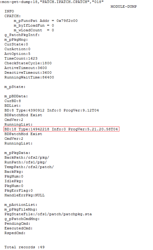
:mon-get-dump:18,"PATCH.IPATCH.CPATCH","018"
The numbers in red represent the slot ID of the active system control board.
The command output indicates that the version of the active system control board is empty (the ProgVer field behind the slot ID of the active system control board is empty, as shown in the following figure).
[Root Cause]
After the active system control board starts from a reset, the patch package module issues a command to the software management module to query the software version. Because the CPU is busy, the software management module does not send the software version to the patch package module within the timeout period. As a result, the query for the software version times out, and the software version of the active system control board recorded in the patch package is empty. When the patch is installed, the NE software verifies the software version of the active system control board and finds that it is not consistent. The verification fails, and the installation of the hot patch for the active system control board is stopped.
[Impact and Risks]
A patch cannot be installed for the active system control board. Issues which can be resolved by installing a hot patch remain unresolved.
Measures and Solutions
Preventive measure:
Before installing a patch, run the following command to query whether the version of the active system control board recorded in the patch package is empty:
:mon-get-dump:18,"PATCH.IPATCH.CPATCH","018"
The numbers in red represent the slot ID of the active system control board.
In normal cases, the ProgVer field behind the slot ID of the active system control board records the detailed version number, as shown in the following figure.

When exceptions occur, the ProgVer field behind the slot ID of the active system control board is empty, as shown in the following figure.


If the version is empty, warm reset the active system control board, or perform an active/standby switchover between the system control boards (for details, see recovery measures). Then, query the software version of the active system control board again to ensure that the software version is recovered.
Recovery measures:
5. When possible, warm reset the active system control board.
6. If an NE houses an active system control board and a standby system control board, a patch has been installed on the standby system control board, and batch backup operations on the active and standby system control boards are complete, then manually trigger an active/standby switchover between the active and standby system control boards to resolve the issue when possible.
Solution:
Upgrade the NE software to V100R010C03SPC220 (which will be released in the first quarter of 2015) or a later version, in which the patch going-online mechanism of the active system control board is optimized and the query for the software version of the active system control board will not time out.
[Rectification Scope and Time Requirements]
N/A
[Rectification Instructions]
N/A
[Appendix]
N/A
[Inspector Applicable or Not]
Use the inspector to check the entire network. Upon detection of an NE that is suspected to have this issue, it is recommended to perform the recovery measures and then upgrade the NE.
Version of the inspector: SmartKit V200R009C00SPC201 or later
Inspector upgrade package:
Common_Inspector_V200R009_ON_20140909163631680.exe
Inspector_V200R009_ON_OptiX OSN 1500, OptiX OSN 1500+,+_20140909163631780.exe
Test case name (which will be released at the end of September 2014): Check whether the version number of the active system control board cannot be obtained and the hot patch cannot take effect.

More related:

Installing the U2000 Client on Windows